You have finalized the purchase contract, confirmed the equipment specifications, and are now awaiting the shipping schedule. The machine is on its way — but the factory floor still needs to be ready to receive it. This is the stage where many buyers underestimate the preparation involved, and where delays most often occur. Getting the installation environment right before the equipment arrives is not just a matter of convenience; it directly determines how quickly you move from container unloading to first production run.
In this article, we will explore the full scope of site requirements, infrastructure specifications, and preparation steps needed to install a sandwich panel production line successfully.
Site Requirements for a Sandwich Panel Line
Before the first shipping container is opened, your facility must meet a defined set of physical and infrastructural conditions. These are not preferences — they are engineering prerequisites.
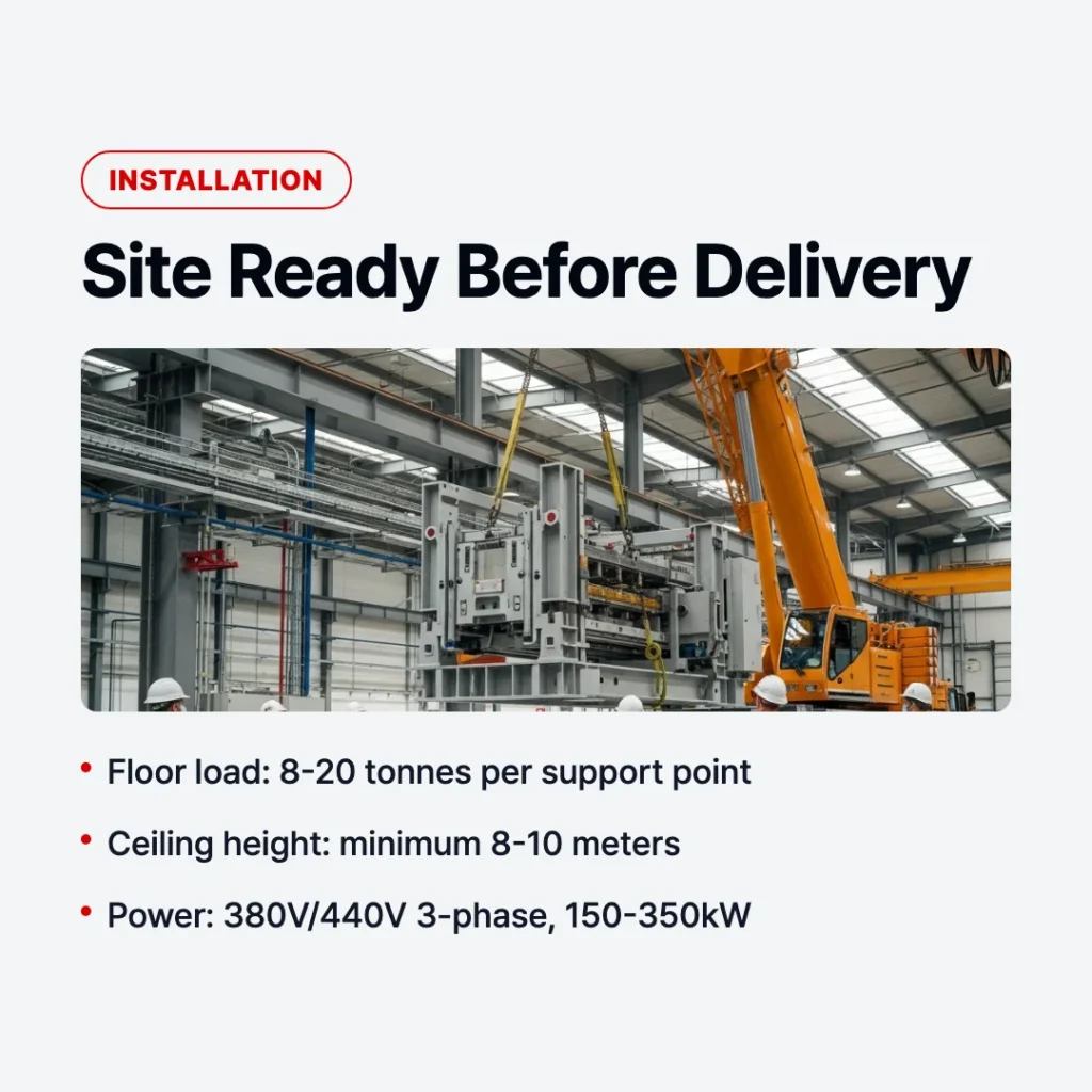
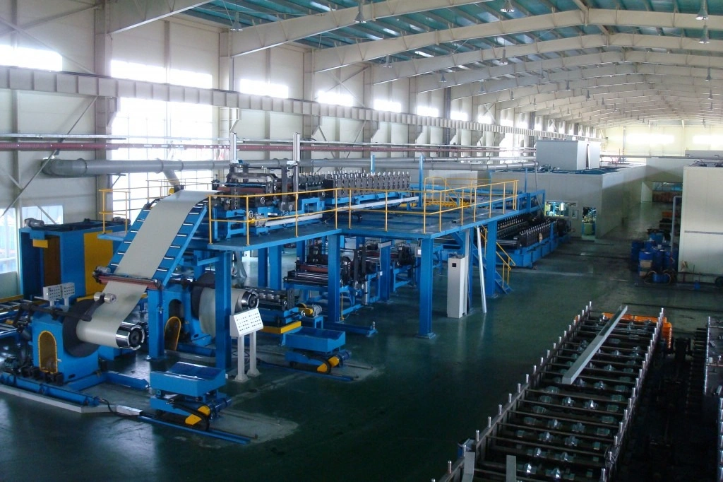
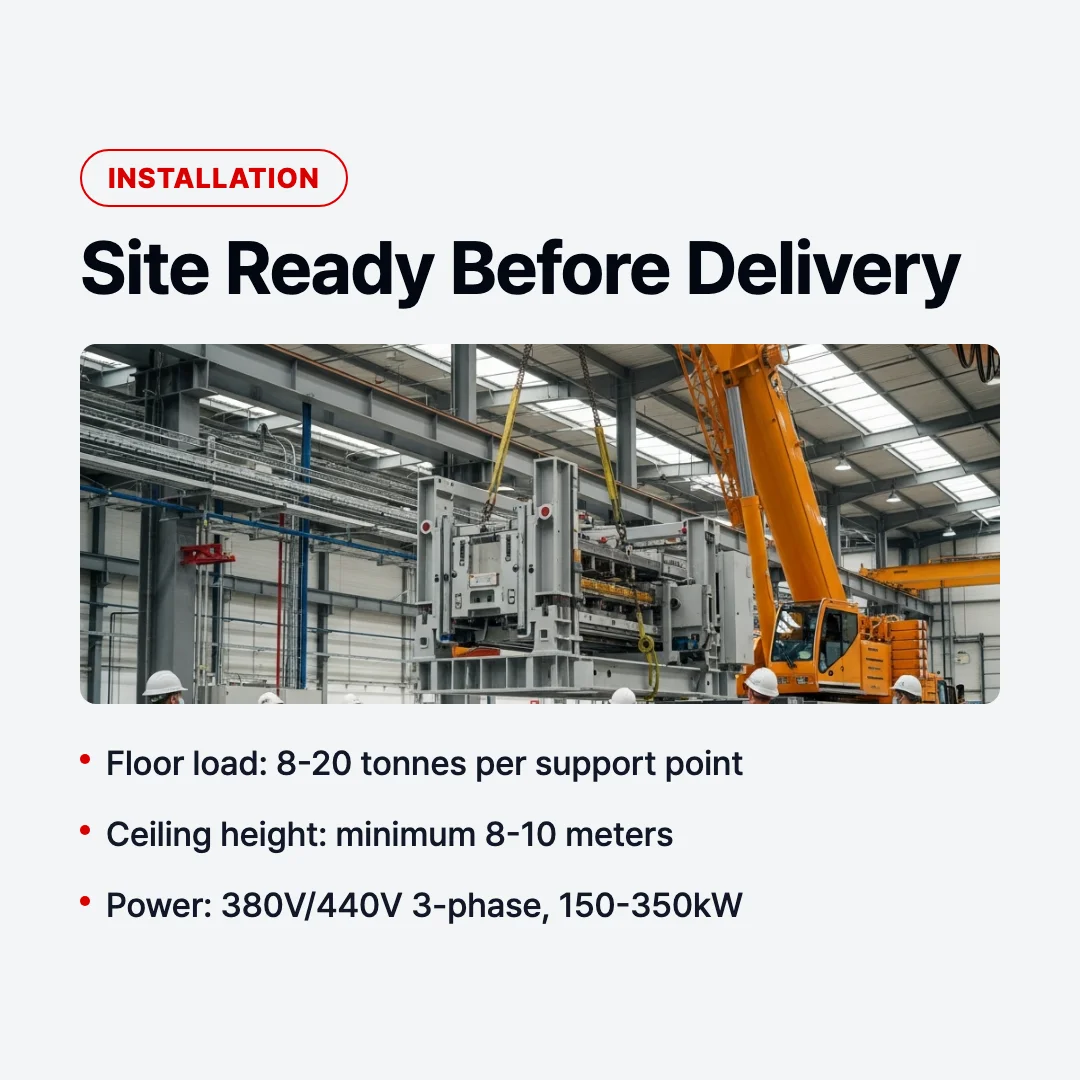
Floor load capacity is the starting point. A full continuous sandwich panel line, including the double belt press, forming stations, roll formers, and stacking systems, can exert concentrated floor loads ranging from 8 to 20 tonnes per support point, depending on machine scale. The slab must be engineered accordingly. If your facility was originally designed for light manufacturing or warehousing, a structural assessment is essential before installation begins.
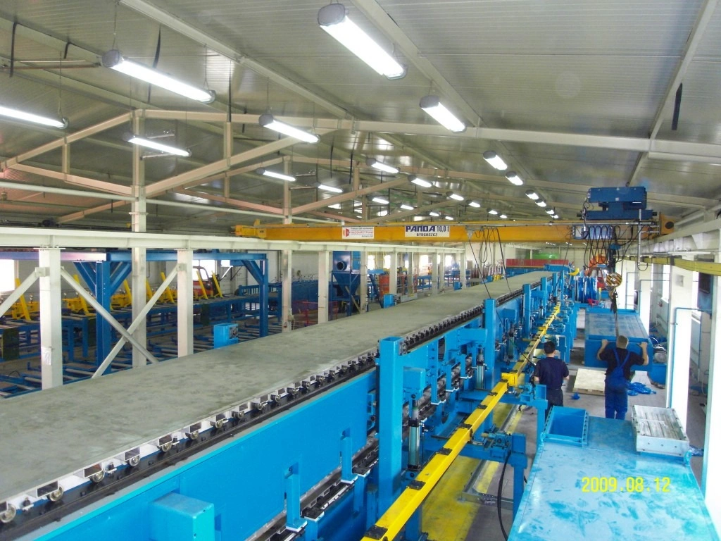
Ceiling height is equally critical. The minimum recommended clear height for a standard continuous line is 8 meters, but facilities handling wide-format panels or integrated coil handling towers will require 10 meters or more. This ceiling clearance is necessary not only for the machine profile itself but for overhead crane access, which is required during assembly and for coil loading during ongoing production.
Power supply must be three-phase industrial current, typically at 380V (50Hz) for European and Asian configurations, or 440V (60Hz) for North American installations. The total connected load for a standard PU/PIR continuous line — including the press drive system, electrical heating zones, conveyor motors, and control panels — typically falls between 150 kW and 350 kW. Your incoming supply transformer must be sized to accommodate peak load demand, not average consumption.
Crane access along the full machine length is required for assembly. A bridge crane with a minimum 5-tonne capacity and coverage across the entire bay width is standard. If your facility does not have an installed crane, a temporary crane or mobile gantry system must be arranged before the installation team arrives.
Ambient temperature in the production hall must remain between 15°C and 30°C during installation and commissioning. For facilities in cold climates, this means the hall must be enclosed and heated before work begins. Foam chemistry — particularly PU and PIR systems — is highly sensitive to temperature variation, and attempting to calibrate foam parameters in an uncontrolled thermal environment will produce unreliable results during trial runs.
For a broader view of the equipment types and their respective footprint characteristics, see Sandwich Panel Production Line: Types, Technology & How to Choose.
Foundation and Floor Specifications
The civil engineering requirements for a sandwich panel line are more demanding than most factory equipment, primarily because of the machine’s length and the precision tolerances required for consistent panel production.
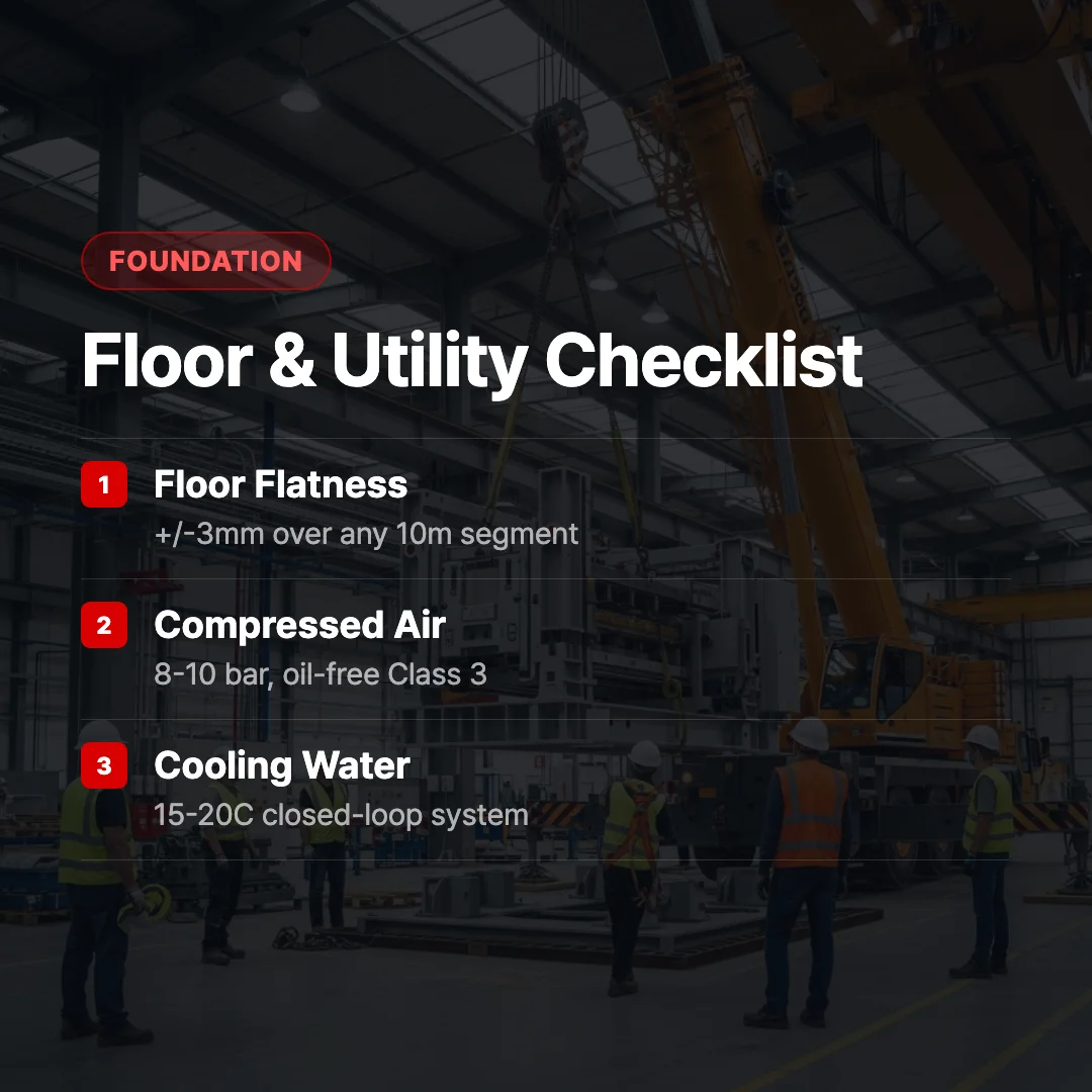
A typical continuous line spans 40 to 80 meters in length. Across this distance, floor flatness must be maintained within ±3 mm over any 10-meter segment. This is not a tolerance that standard industrial construction achieves automatically — it requires deliberate specification at the concrete pour stage, followed by measurement and grinding as needed before installation begins.
Vibration isolation is a requirement often overlooked in the planning phase. The double belt press generates rhythmic mechanical loads during operation. If the slab is directly connected to adjacent structures — columns, walls, or shared foundations — vibration transmission can affect both the machine’s precision and the integrity of nearby structural elements. Expansion joints and isolation pads under the machine base frames address this risk.
Anchor bolt layout must be coordinated with the machine supplier before concrete is poured. The foundation drawing provided by the manufacturer specifies the exact position, diameter, and embedment depth of all anchor points. In many installations, these anchor bolts are cast into the slab in advance, which eliminates the need for core drilling later and produces a stronger connection. If the slab is already poured, post-installed chemical anchors can be used, but only with prior approval from the equipment supplier’s structural engineer.
Pit requirements apply specifically to double belt press configurations. The belt press lower section requires access from below for belt tensioning, inspection, and maintenance. A recessed pit — typically 600 to 1,000 mm deep and running the full length of the press section — must be formed in the slab. The pit edges must be finished flush and smooth to prevent edge failure under load.
A definition that is useful here: the “machine datum level” is the reference elevation from which all vertical dimensions are set during installation. This level must be established by survey before assembly begins and must remain consistent across the entire machine length.
What happens if the floor flatness does not meet the ±3 mm specification?
Out-of-tolerance floors cause the machine base frames to rack under leveling, which distorts the alignment of the belt press, roll formers, and cutting station. The result is inconsistent panel thickness, edge gaps, and recurring mechanical issues at joints between machine sections. Floor grinding or epoxy leveling compound application is far less expensive than correcting production quality problems after startup.
Utility Connections and Infrastructure
A sandwich panel line requires several utility systems to be in place and tested before commissioning can begin. The following checklist covers the standard requirements for a PU/PIR continuous line. Intermittent or batch configurations share most of these requirements, though at lower capacity levels.
Compressed air system
- Supply pressure: 8 to 10 bar, maintained continuously during production
- Flow rate: minimum 500 liters per minute for a standard continuous line
- Air quality: dry and oil-free (Class 3 per ISO 8573-1); contamination causes actuator failure and foam metering errors
- Distribution: main header pipe sized at minimum 50 mm internal diameter; drops to machine stations at 25 mm
- Dryer and filtration unit: installed upstream of all machine connections, not just at the compressor
Water cooling system
- Purpose: press platens, chemical component temperature control (polyol and isocyanate), hydraulic oil coolers
- Cooling water flow: typically 20 to 50 liters per minute depending on press size
- Supply temperature: 15°C to 20°C; supply from a closed-loop chiller is preferred over open tower systems
- Piping: dedicated supply and return lines run to the machine; connections via flexible hose drops at each cooling point
- Water quality: treated and inhibited to prevent scale buildup in narrow-bore platen channels
Electrical infrastructure
- Main panel location: positioned adjacent to the machine electrical room, within 10 meters of the machine main cabinet
- Cable routes: conduit or cable tray installed before machine arrival; routing coordinated from the supplier’s electrical layout drawing
- Earth bonding: all machine sections connected to a common earth bar; earth resistance below 4 ohms
- Emergency stop circuit: hardwired loop around the full machine perimeter; tested before first power-on
Chemical storage and ventilation
- Polyol and isocyanate storage: temperature-controlled room adjacent to the production hall, maintaining 20°C to 25°C
- Ventilation: minimum 10 air changes per hour in the foaming section of the production line; local exhaust at the mixing head position
- Spill containment: bunded floor in chemical storage area; capacity equal to 110% of the largest single container
- Fire suppression: foam or CO2 system in chemical storage; confirmed with local fire code before installation
For technical details on the foaming process and press configuration, see Continuous Sandwich Panel Line: Technology, Benefits & Applications.
Installation Timeline and Commissioning Steps
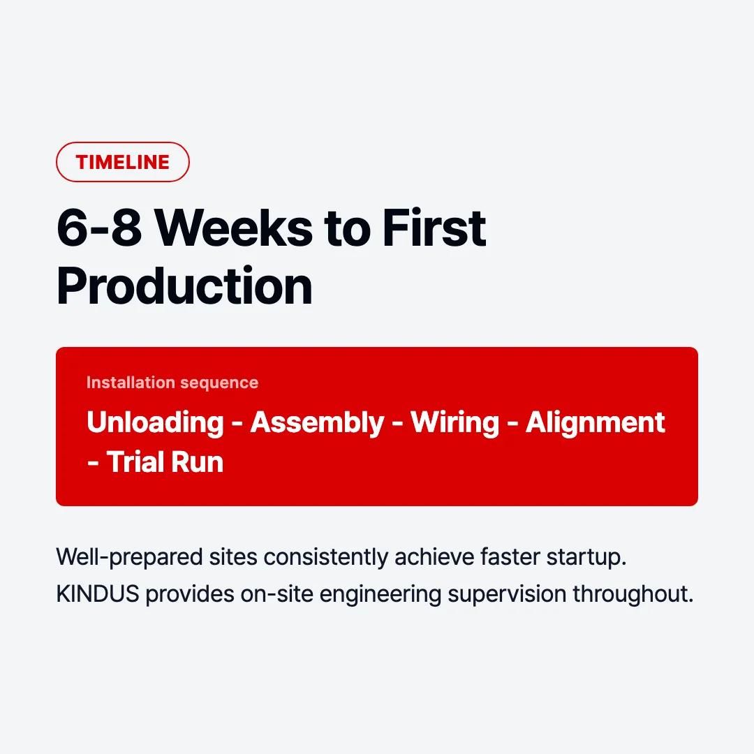
A structured installation sequence minimizes idle time and ensures that each phase is completed correctly before the next begins. The following is a representative timeline for a standard continuous PU/PIR line.
Week 1 to 2: Container unloading and component sorting
Shipping containers arrive in multiple loads, often staggered across several days. Each component is unloaded using the facility crane and placed in a designated staging area according to the assembly sequence. A packing list check against the supplier’s delivery record is completed during this phase. Any damaged or missing items must be reported within the inspection window defined in the supply contract.
Week 2 to 4: Mechanical assembly
Machine sections are positioned on the foundation in sequence: entry station, coil decoiler, profiling rolls, double belt press, side press panels, cutting station, and exit conveyor. Base frames are set to the datum level and anchor-bolted. Sections are bolted together and the belt is threaded through the press. Roll former sets are installed and preliminary gap settings are made.
Week 4 to 5: Electrical wiring and control panel connection
All power and signal cables are routed and terminated. The control system is powered up section by section, with interlocks and safety circuits tested before any drive operation. PLC firmware is loaded and the operator interface is configured.
Week 5 to 6: Alignment and calibration
This is the most technically demanding phase. Press parallelism, belt tracking, conveyor alignment, and cutting station squareness are all set using precision instruments. Chemical metering pumps are calibrated for flow rate and ratio. Heating zones are brought to temperature and profiled. These settings directly determine panel quality and must be documented for future reference.
Week 6 to 7: Trial run and foam development
Short production runs are conducted to verify that foam fill, skin adhesion, thickness uniformity, and edge quality meet specification. Foam chemistry parameters — cream time, gel time, density, and compressive strength — are tested on samples from each run. Adjustments are made iteratively until production panels pass quality checks.
Week 7 to 8: Full production test
The line runs at production speed for a defined quantity of panels — typically one to three full shifts. Output is measured against the contracted specification. Any remaining mechanical or chemical adjustments are completed during this phase.
KINDUS dispatches factory-trained installation engineers to supervise the full sequence on-site. The supervision team includes both mechanical and electrical specialists, and their schedule is coordinated with the client’s site preparation completion date. Clients who complete site readiness before the equipment arrives consistently achieve shorter installation timelines.
KINDUS Installation Support
The supply of equipment is one part of the engagement. Getting that equipment running correctly in your specific facility, with your operators, is the more operationally significant challenge — and it is where long-term production reliability is determined.
KINDUS provides a structured installation and commissioning package that covers the full scope from container arrival to validated production output. The support framework includes the following components.
On-site engineering supervision. A dedicated team of mechanical and electrical engineers is present throughout the installation and commissioning period. This team is responsible for quality of installation, resolution of any site-specific challenges, and sign-off on all alignment and calibration records. Their presence is not advisory — they are directing the process.
Operator training. Structured training is conducted in parallel with the commissioning phase, so operators learn on the actual line in their own facility. Training covers daily startup and shutdown procedures, routine maintenance tasks, fault diagnosis using the HMI, and chemical handling protocols. A training record is completed for each operator, and supplementary documentation is left on-site.
Commissioning spare parts. A commissioning spare parts kit is included with every line delivery. This kit contains the consumable and wear items most likely to require replacement during the first months of production: belt wear components, mixing head spares, metering pump seals, and sensor elements. The kit is itemized and stored in a designated location during commissioning.
After-sales technical support. Following commissioning sign-off, KINDUS maintains a direct technical support channel for production and maintenance questions. Remote diagnostics are available via the control system’s data connection for clients who choose to activate this function. Scheduled follow-up visits are available as part of extended service agreements.
The combination of 30 years of production line manufacturing experience and over 170 completed projects across international markets means that KINDUS engineers have encountered the full range of site conditions, utility constraints, and operational challenges that arise during real-world installations — and have developed practical responses to each.
Frequently Asked Questions
What floor space is needed for a standard continuous line?
The production hall footprint depends on line length and panel format, but a practical planning figure for a standard continuous PU/PIR line producing panels up to 1,200 mm wide is a clear floor area of 80 meters in length by 15 meters in width. This accommodates the machine body, entry and exit material handling, operator walkways, and chemical storage proximity. Additional space is required if an integrated coil storage area or finished panel stacking buffer is included in the layout.
How long does installation take from container arrival to production startup?
For a well-prepared site — meaning all civil works, utility connections, and crane access are in place before equipment arrives — the installation and commissioning period for a standard continuous line is 6 to 8 weeks. Sites where preparation work is still ongoing when equipment arrives will see this timeline extend, sometimes significantly. The civil and utility preparation phase, which is the client’s responsibility, typically takes 8 to 12 weeks and should begin immediately after the equipment order is confirmed.
Is operator training included in the installation package?
Yes. Hands-on operator training is a standard part of the commissioning scope, not an optional add-on. Training is conducted on the client’s own line, in the client’s facility, during the commissioning and trial production phase. This means operators are trained on the specific configuration, chemistry settings, and parameters that have been established for their line — not on a generic machine in a demonstration facility. A documented training record is completed for each trained operator before the installation team departs.
There is a direct relationship between the quality of site preparation and the speed and smoothness of installation. Factories that invest time and attention in civil works, utility commissioning, and pre-arrival coordination consistently achieve faster startup timelines and lower commissioning costs. The machine is a precision instrument — it performs to its rated capability when the environment supporting it has been properly engineered.
There is a direct relationship between site preparation quality and installation speed. If you are comparing which line configuration fits your facility footprint and utility capacity, you can review the full KINDUS production line range below.